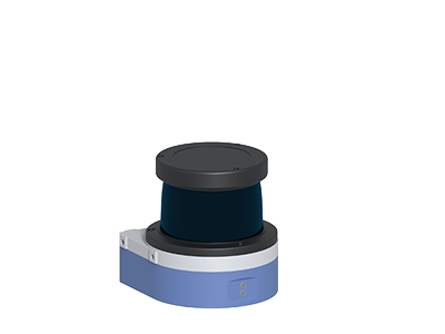
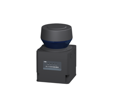
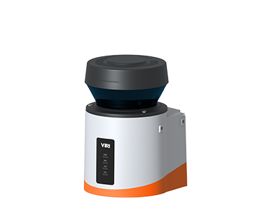
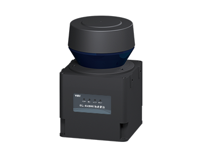
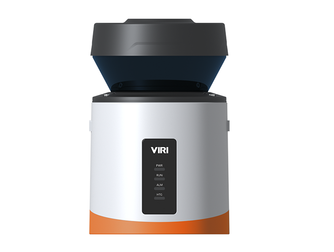
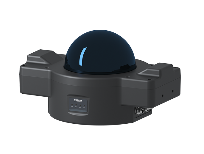
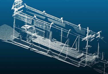
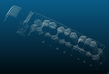
The TH-9120A lidar performs 3D high-precision scanning of stationary targets, with a scanning cycle ranging from 3 to 64 seconds(adjustable),
such as scanning the internal contour and vehicle posture before automatic loading.
The TH-91 series is supporting both indoor and outdoor applications. It is a 3D scanning type, with the maximum line scanning frequency up to 50Hz and the minimum line scanning angle resolution of 0.125°. It adopts industrial-grade protective design, which can meet the strict requirements for precision and reliability of mining and metallurgical industries in applications such as loading monitoring, automatic coiling, material level height, material level volume, and 3D point cloud.


Emission frequency144000Hz

Scanning frequencyLine scan:50Hz ;Field scan:0.25Hz

Scanning range20m@10%

Scanning angleLine scan:155° ;Field scan:55°

Light resistance grade80000lx

Angular resolutionLine scan:0.167° ;Field scan:0.55°

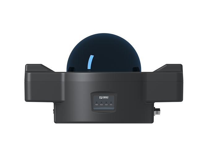

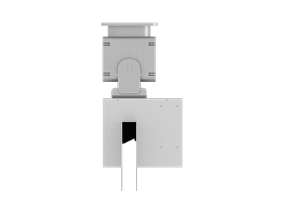
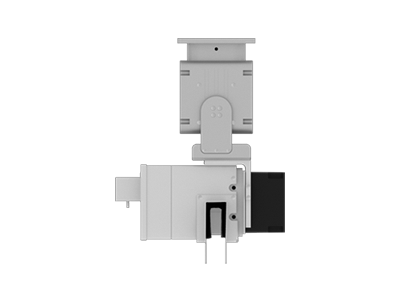
Product Model
TH-9120A
Dimensions (L x W x H)
330×225×188mm
Weight
<4.5kg
Laser class
1,eye-safe (IEC 60825-1)
Laser source
905nm
Emission frequency
144KHz
Scanning range
20m@10%
Scanning frequency
Line scan:50Hz ;Field scan:0.25Hz( typical3s,3~64s/field)
Aperture angle
Line scan:155° ;Field scan:70°
Angular resolution
Line scan:0.125° ;Field scan:0.022°@64s/cycle
LIDAR (Light Detection and Ranging) typically utilizes a three-dimensional Cartesian coordinate system to describe the spatial positions of laser scan point cloud data. This coordinate system is often referred to as the LIDAR coordinate system or scanning coordinate system.
In the LIDAR coordinate system, the origin is typically located at the center of the LIDAR sensor, with the X-axis, Y-axis, and Z-axis representing different directions. The specific direction definitions may vary depending on the installation method and application scenario of the LIDAR sensor. For instance, in some cases, the X-axis may represent the forward direction of a vehicle, the Y-axis represents the lateral direction, and the Z-axis is perpendicular to the ground pointing upward. During the LIDAR scanning process, each laser point has a corresponding coordinate value in this coordinate system, which describes its position in three-dimensional space. By processing and analyzing these point cloud data, we can obtain three-dimensional information about the surrounding environment, such as terrain, buildings, vegetation, and so on.
"Lidar detection range is not far enough" indicates that the lidar system is unable to detect objects at sufficiently long distances. This limitation may be due to factors such as its power output, beam quality, receiver sensitivity, atmospheric conditions (e.g., fog, rain), scanning mode, or the reflectivity of the target objects. In applications that require long-range detection, a more powerful lidar system or alternative technologies may be needed to extend the detection range.
Data Synchronization: Firstly, it is necessary to ensure that the LiDAR and camera are synchronized in both time and space. This means they must be able to capture information from the same scene simultaneously, and the data needs to be precisely aligned in time. Feature Extraction and Matching: Camera tracking systems typically extract key feature points from video sequences, such as corner points, edge points, or texture points. These feature points exhibit good stability and distinguishability between frames, enabling their use in subsequent tracking and pose estimation. The LiDAR can provide 3D information about the scene, including the position and shape of objects. By fusing data from both sensors, more rich feature points can be extracted and matched more accurately. Fusion Algorithm: To achieve collaborative tracking between LiDAR and cameras, a fusion algorithm needs to be developed to integrate their data. This algorithm can utilize techniques such as probabilistic models and Kalman filters to fuse the 3D data from the LiDAR with the 2D image data from the camera, resulting in more accurate tracking results. Collaborative Work: During collaborative tracking, the LiDAR and camera need to work together. The LiDAR can provide depth information about the scene and the 3D positions of objects, helping the camera determine the precise location of target objects. The camera, on the other hand, can provide appearance information about the targets, such as color and texture, assisting the LiDAR in identifying target objects more accurately. Through their collaborative work, faster and more accurate tracking can be achieved. Optimization and Feedback: In practical applications, it may be necessary to continuously optimize the fusion algorithm and collaborative work mechanism to improve tracking accuracy and stability. At the same time, a feedback mechanism should be established to facilitate timely adjustments and corrections in case of deviations during the tracking process.
The recognition capability of LiDAR is closely related to the reflectivity of objects. Reflectance refers to the percentage of incident radiation energy that is reflected by an object. Different objects have different reflectances, which mainly depend on the nature of the object itself, such as the wavelength of the electromagnetic wave and the angle of incidence.
When LiDAR detects a target object, it emits a laser beam and receives the reflected laser light from the object's surface. The reflectance of the object determines the intensity of the reflected light received by LiDAR. If an object has a higher reflectance, then LiDAR will receive more reflected light, thus improving its recognition capability for that object. Conversely, if an object has a lower reflectance, LiDAR will receive less reflected light, and the recognition capability will decrease accordingly.
Therefore, the recognition capability of LiDAR is closely related to the reflectance of objects. In practical applications, to improve the recognition capability of LiDAR, one can choose objects with high reflectance as targets, or increase the emitted laser power and optimize the focusing of the laser beam to enhance the intensity of the received reflected light, thus improving the recognition capability.
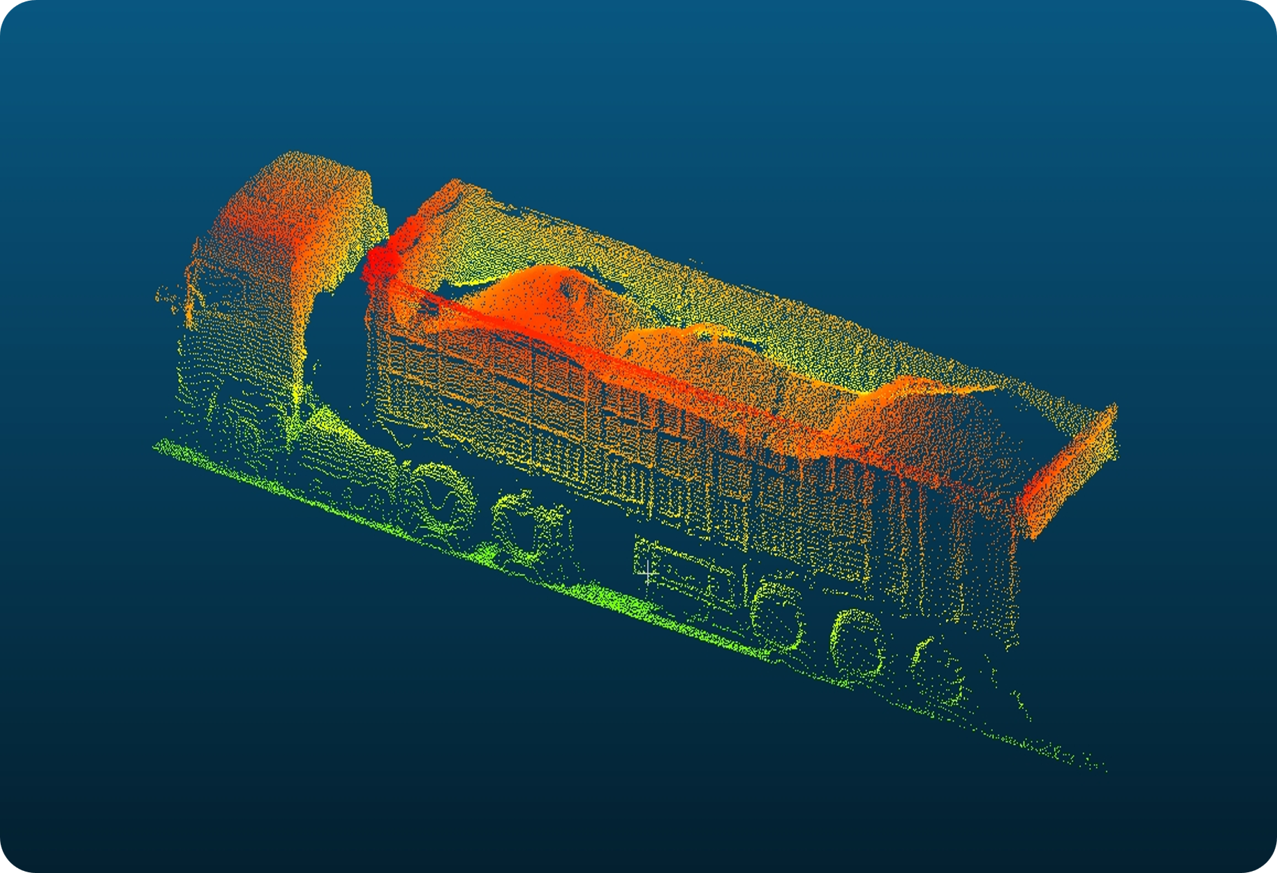
Truck Cargo Identification and Loading Monitoring
Cargo Identification and Loading Detection
Vehicle Cargo Recognition and Loading Inspection
© Copyright Baoding Galaxy Electronic Technology Co.,Ltd. 2024. All rights reserved.冀ICP备05000380号-1 Privacy Policy
Design by: Bjszhd